

Innovative Electric Solutions

Inside the Control Panel Design and Build Process
Howie Heerdt • September 18, 2026
How precision engineering, custom panel fabrication, and rigorous testing turn complex automation into reliable plant floor operations.
Behind every automated production line, municipal water system, and processing facility is a control system responsible for keeping equipment operating safely and predictably.
The industrial control panel brings that system together. It distributes power, connects field devices, houses automation hardware, and gives operators the information and controls they need to manage the process.
Building one requires far more than mounting components inside a steel enclosure. A dependable panel begins with careful requirements gathering and continues through engineering, fabrication, testing, installation, and commissioning. Decisions made at every stage can affect safety, maintainability, future expansion, and plant uptime.
Here is what a professional control panel design and build process looks like.
Phase 1: Define the Operating Requirements
Before schematics are created or components are ordered, engineers must understand how the panel will operate in the real world.
That starts with the process itself. What equipment will the panel control? How will operators interact with it? What happens during a fault, emergency stop, or loss of communication? Does the system need to exchange data with existing equipment or a plantwide supervisory control and data acquisition system?
The project team also evaluates:
- Operating environment: Indoor or outdoor location, temperature, dust, moisture, washdown exposure, corrosion, and any hazardous-location requirements.
- Power requirements: Available voltage, connected loads, branch-circuit protection, grounding, and short-circuit current rating.
- Control architecture: PLCs, HMIs, VFDs, motor starters, safety devices, instrumentation, remote I/O, and network communications.
- Maintenance needs: Component accessibility, diagnostic visibility, spare capacity, documentation, and replacement-part availability.
- Future expansion: Space, power, I/O, and communications capacity for anticipated changes.
This phase establishes the design criteria for the entire project. Thorough planning here reduces costly revisions during fabrication and installation.
Phase 2: Develop the Schematics and Panel Layout
Once the requirements are established, controls engineers translate them into electrical schematics, bills of material, and physical panel layouts.
Component selection is based on more than voltage and current. Engineers must consider environmental ratings, available fault current, heat generation, communication compatibility, safety requirements, and the availability of replacement parts.
The physical arrangement matters, too. A well-planned layout:
- Maintains appropriate separation between power and control wiring
- Creates clear pathways for field wiring
- Provides adequate spacing and ventilation around heat-producing equipment
- Makes terminals and components easier to inspect and service
- Leaves practical room for approved future additions
Thermal management is especially important when a panel contains VFDs, power supplies, transformers, or other heat-producing devices. Depending on the application, the design may require ventilation, heat exchangers, air conditioning, or other environmental controls.
The enclosure must also match the installation environment. For example, a NEMA Type 12 enclosure may be appropriate for certain indoor industrial settings, while a Type 4X enclosure may be needed where corrosion or hose-directed water is a concern. Classified locations require equipment and protection methods specifically approved for those conditions.
Phase 3: Fabricate and Wire the Panel
After the design is reviewed and approved, the project moves into fabrication.
Technicians first prepare the enclosure and back panel, mounting wire duct, DIN rail, disconnects, breakers, transformers, drives, controllers, and other components according to the approved layout.
Point-to-point wiring then connects every device to the corresponding location shown in the schematic. Consistent workmanship is essential. Conductors must be properly sized, routed, terminated, identified, and torqued according to the applicable design requirements and manufacturer instructions.
A disciplined fabrication process typically includes:
Stage Key Work Mechanical layout Mounting rails, wire duct, operators, disconnects, and components with planned spacing Panel wiring Routing and terminating power, control, safety, and communication circuits Identification Labeling conductors, terminals, components, and field connection points to match the drawings Workmanship review Checking conductor routing, bend radius, grounding, separation, and terminal integrity Documentation updates Recording approved field or fabrication changes so final drawings match the finished panel.
Clear labeling and accurate documentation make a major difference after installation. When technicians can quickly trace a circuit or identify a terminal, troubleshooting becomes faster and less disruptive.
Phase 4: Inspect and Test the Completed Panel
A panel should be verified before it reaches the jobsite. Factory acceptance testing helps identify wiring, configuration, or communication issues while the system is still in a controlled shop environment.
Testing may include:
- Visual inspection of component placement, wiring, labels, and grounding
- Verification of terminal torque and mechanical connections
- Point-to-point continuity testing against the electrical schematics
- Confirmation of power-supply and control-voltage outputs
- PLC input and output checks
- Safety-circuit and interlock testing
- HMI, network, and device communication checks
- Functional simulation of operating sequences when the project allows
Any issues found during testing are corrected and documented before shipment. The result is a panel that arrives better prepared for installation and startup.
Phase 5: Install, Integrate, and Commission the System
Panel construction is only part of the job. The control system must also work with the facility’s power distribution, field equipment, instrumentation, machinery, and communications network.
During installation and commissioning, technicians and controls engineers connect motors, sensors, valves, safety devices, and other field equipment. They verify signal direction, motor rotation, device calibration, network communication, alarms, interlocks, and programmed operating sequences.
Commissioning also gives the project team an opportunity to validate the system with operators and maintenance personnel under actual operating conditions. Final drawings and operating documentation should reflect the completed installation.
Why an Integrated Electrical and Controls Team Matters
Many panel projects cross several disciplines. Electrical engineering, control programming, panel fabrication, field installation, and startup must all work from the same design intent.
Morton Electric brings
electrical contracting and automation expertise together within one integrated team. That approach can simplify communication, reduce coordination gaps, and provide a consistent point of responsibility from initial design through commissioning. Morton Electric designs and builds custom PLC panels, VFD enclosures, motor-control systems, and other
industrial control panel solutions for manufacturing, municipal, commercial, and infrastructure applications. Planning a new system, equipment upgrade, or controls retrofit? Call (812) 402-0900 or request a consultation to discuss your application. Claim Check
You might also like

Key Considerations for Choosing the Right Partner for Your Industrial and Commercial Power Needs
Compare the advantages of Tesla Powerwall storage against traditional standby generators before making your next backup power investment.
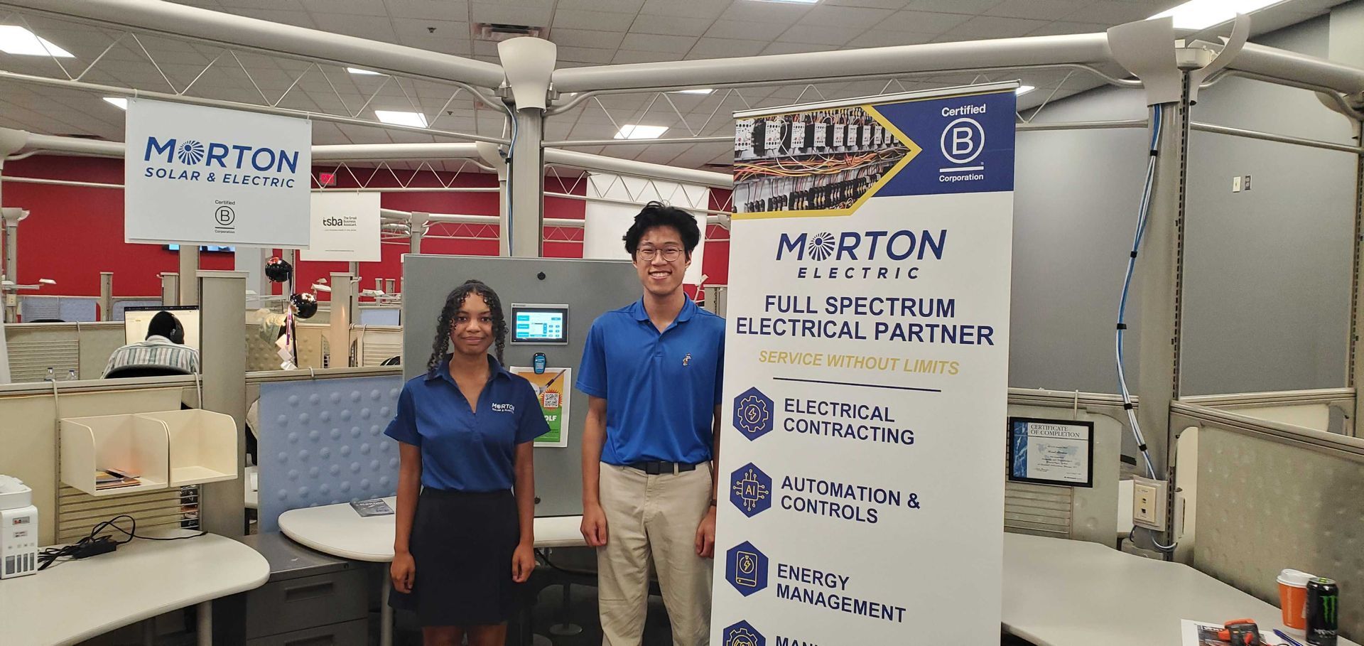
At Morton Electric, we believe that true innovation happens at the intersection of industry, education, and real-world experience. That’s why we’re thrilled to share two major developments that reflect our commitment to advancing industrial technology and developing the workforce of tomorrow.